EN
EN
 AR
AR
 BG
BG
 HR
HR
 CS
CS
 DA
DA
 FR
FR
 DE
DE
 EL
EL
 HI
HI
 PL
PL
 PT
PT
 RU
RU
 ES
ES
 CA
CA
 TL
TL
 ID
ID
 SR
SR
 SK
SK
 SL
SL
 UK
UK
 VI
VI
 ET
ET
 HU
HU
 TH
TH
 MS
MS
 SW
SW
 GA
GA
 CY
CY
 HY
HY
 AZ
AZ
 UR
UR
 BN
BN
 LO
LO
 MN
MN
 NE
NE
 MY
MY
 KK
KK
 UZ
UZ
 KY
KY


Kuelewa Msingi wa Mabaharia kwa Kupunguza Vikwazo
Jinsi ya Mabaharia Kuwazuia Mikondo ya Vikwazo: Upinzani wa Kuvutia vs. Kifupi
Baharia huwazuia mikondo ya vikwazo kupitia upinzani wa kuvutia ( X L = 2πfL ), ambao huongezeka kwa njia ya mstari na kifupi. Kwa sababu vikwazo vinatokea katika mara nyingi za msingi (k.m., 250 Hz kwa vikwazo vya 5 katika mfumo wa 50 Hz), baharia hutoa upinzani mkubwa zaidi kwa hayo kuliko kwa msingi wa 50/60 Hz. Upinzani huu unaotegemea kifupi unapunguza mikondo ya vikwazo ya kifupi juu ya kufikia vifaa vya chini au mitandao ya umeme. Juu ya mpangilio wa vikwazo, juu ya mgawanyo wa voltage kwenye baharia kwa mikondo hiyo—hivyo hujenga uwezo wa kuvutia mdogo tu. Kwa mfano, baharia ya mstari ya kawaida ya asilimia 3 au 5 (iliyopangwa kwa kifupi cha msingi) mara nyingi inapunguza jumla ya uharibifu wa mikondo ya vikwazo (THD i ) kwa 30–50%, kulingana na upinzani wa mfumo na vipengele vya mzigo.
Aina za Mizinga na Ujenzi: Mizinga ya Hali ya Hewa dhidi ya Mizinga ya Chuma kwa Matumizi ya Mtandao
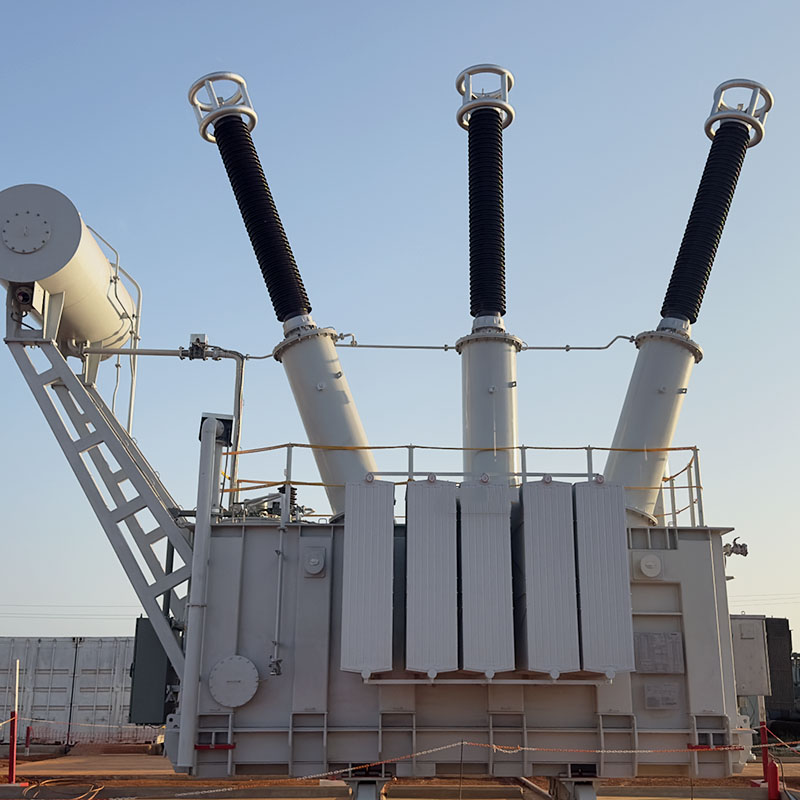
Ujenzi wa msingi unavyoathiri kwa kiasi kikubwa utendaji, ukubwa, na uwezo wa kushinda vibaya. Mabahadia ya hewa (air-core) hutumia vitu visivyokuwa na mali za umagnetismu (kama vile hewa au barafu ya glasi) na hutoa upungufu wa kawaida (linear inductance) bila kujitokeza—havijasatishwa hata chini ya mikondo ya vibaya ya juu sana. Uthabiti wao, utunzaji mdogo sana, na ustawi dhidi ya kusatishwa (saturation) unawafanya kuwa bora zaidi kwa matumizi ya nje, volti ya juu, au matumizi ya mtandao unaohitaji uaminifu mkubwa ambapo upungufu uliosalitiwa (predictable impedance) unahitajika sana. Mabahadia ya chuma (iron-core) hutumia chuma kilichopakuliwa (laminated steel) ili kugawanya uwanja wa umagnetismu, kufikia upungufu wa juu kwa kila kiasi cha kiasi (higher inductance per unit volume) na ukubwa mdogo zaidi. Hata hivyo, upungufu wao unapungua chini ya mikondo ya ziada kwa sababu ya kusatishwa kwa msingi, kinachodhoofisha uwezo wa kupunguza vinyago (harmonic suppression) wakati unaohitajika zaidi. Kwa hiyo, mabahadia ya hewa yanapendwa zaidi pale ambapo viwango vya vibaya vya mtandao ni vyenye nguvu au uaminifu ni muhimu sana; zile za chuma zinatumika katika mahitaji ya ndani ambapo nafasi ni machafu na kiwango cha vinyago na hatari ya vibaya ni chini.
Kukokoa Mabahadia Kulingana na Mtandao wa Vinyago na Mahitaji ya Mtandao
Uchaguzi wa Kipimo cha Uwezekano (2–5%) Uliofanana na Miradi ya Uharabu Mkuu
Kiwango cha uwezekano wa kujenga—kilitazamwa kama asilimia ya upinzani wa mfumo katika kifupi cha msingi—ni kiparameta cha kwanza cha ukubwa kwa kudhibitisha vikwazo. Kijenzi cha asilimia 2 kinatoa kudhoofisha kidogo na kupungua kidogo cha utaratibu wa umeme, kinachofaa katika mazingira yenye vikwazo vidogo au katika matumizi yanayohitaji udhibiti bora wa utaratibu wa umeme. Kijenzi cha asilimia 5 kinatoa kudhibitisha kikali zaidi, hasa dhidi ya vikwazo vya namba 5 na 7 vinavyotokana mara nyingi na kijenzi cha pili cha mstari wa sita (k.m., VFD, mabadilisho ya nuru ya jua). Kwa mzigo unaounganishwa kwa vikwazo vya namba 5, kiwango cha asilimia 4–5 ni cha bora; kwa vikwazo vya aina mbalimbali, asilimia 3 inafanya kazi vizuri kama msingi. Kwa namna muhimu sana, chaguzi hii lazima iwe na msingi wa data ya vikwazo iliyosomwa au iliyomodeliwa—si kwa kuhakikisho tu. Kama vile IEEE 519-2022 inasisitiza, utafiti uliothibitishwa wa vikwazo unategua namba za vikwazo vilivyovutia zaidi na huongoza kufanya mpangilio maalumu. Kuchagua kijenzi kikubwa sana kunaweza kusababisha kupungua kikubwa sana cha utaratibu wa umeme na matatizo ya kushirikiana ya mifumo ya kulinda; kuchagua kijenzi kidogo sana kunaweza kuacha vikwazo vilivyobaki vinavyoweza kujaza kivinjari au kusababisha kutetemeka kwa sababu isiyotarajwa.
Kusawazisha Upungufu wa Voltage, Kupunguza THD, na Kusawazisha Ushirikiano wa Ulinzi
Kukadiria kiasi cha kipimo cha kireaktori kinahitaji kusawazisha sababu tatu zinazotegemeana: upungufu wa uta, kupunguza vikwazo vya harmoniki, na usawazisho wa kifaa cha ulinzi. Uzito wa juu unaboresha kupunguza THD lakini hupanua upungufu wa uta wa hali ya kawaida—ambao unaweza kuharibu uwezo wa mafuta au kusababisha alama za uta chini. Kwa upande mwingine, uzito usio kutosha haupunguzi vikwazo vya sasa vya harmoniki, na hivyo kuchangia kuanguka kwa fusit za kondensata, joto la ziada katika mionzi, na udhahania wa uta unaopita mipaka ya IEEE 519. Usawazisho wa ulinzi unongeza ufanisi wa uchunguzi: kireaktori lazima kuzuia uhamisho wa sasa na mkondo wa kushindwa bila kuchelewesha kifaa cha juu cha kuvunjika au relai. Tabia bora inanuanisha kuanza na kireaktori cha asilimia 3 kama kituo kilichothibitishwa, kisha kuboresha kulingana na uchunguzi wa harmoniki na upungufu wa uta unaoruhusiwa (kwa kawaida ≤5% katika mzigo wote). Zana za simulatio kama vile ETAP zinasaidia kuthibitisha mizani ya faida na hasara katika mazingira ya kazi. Wakati wa THD v lazima iwe chini ya 5%, kwa kawaida kipimo cha 4% cha kireaktori hufikia mchanganuo bora—kutoa upungufu wa kuchukua kwa kiasi cha kujadiliwa wakati huhalalisia ustawi wa mfumo na uhai wa ulinzi.
Kuweka Kireaktori Kwa Ajili Ya Kuondoa Ufunguo Na Kuongeza
uhamisho wa Thamani ya k na Kuweka Kireaktori Kwa Ajili Ya Kuondoa Ufunguo wa Usambazaji na Vifaa vya Kuhifadhi Umeme
Kuweka kireaktori kwa usahihi huzuia ufunguo wa usambazaji unaoharibika kati ya upinzani wa kuvutia ( X L ) na upinzani wa kuhifadhi ( X C ) kutoka kwa vifaa vya kuboresha sababu ya umeme (PFC). Parametri muhimu ni thamani ya k -ya k:
k = (X L / X C ) × 100% ,
wapi X L = 2πfL na X C = 1/(2πfC) . Thamani za kawaida za kutengeneza (5.67%–7%) zinabadilisha mzunguko wa usawa wa msambamba chini ya harmoniki kuu—k.m., kipimo cha 7% katika mfumo wa 50 Hz kinaweka usawa kwa takriban 189 Hz, chini ya salama ya harmoniki ya 5 (250 Hz). Hii inaunda baradi ya upinzani wa juu ambayo inalinda mgandamizo wa sasa ya harmoniki ndani ya benki ya kondensaya, ikuzuia kuongezeka kwa sasa, ukovu wa kondensaya kwa sababu ya mzigo wa juu, na miombo ya mstari wa voltage. Data za shirika la umeme zinathibitisha kwamba mfumo usiofunguliwa unaharibiwa hadi 300% zaidi katika matukio ya harmoniki. Kwa hivyo, k -hesabu ya thamani lazima ifanywe kabla ya kufunga PFC yoyote—na daima itarejea vipimo vya halisi vya X C na mfumo X L , si thamani zilizochapishwa kwenye lebo.
Ukaguzi wa Hatari ya Usawa wa Kinyume Katika Upiyaji wa Mfumo wa Umeme unaobadilika
Ukubaliana wa wavu si mara moja tena: ukabadilika kwa muda mfupi wa vyanzo vya nishati ya kisasa, mzunguko wa mzigo, na upanuzi wa mtandao huleta mabadiliko ya kila siku—marahaba ±40% au zaidi. Vifaa vya kujitenga vya kudumu, vilivyoundwa kwa ukubaliana wa kipengele kimoja tu, mara nyingi huwa bila faida au hata hatari chini ya hali za ulimwengu halisi. Kwa hiyo, utamuzi wa kisasa wa ufanisi wa kufanya kazi ya kuvuruga unapaswa kuwa wa kudumu, ukijumuisha:
- Uchunguzi wa ukubaliana wa wakati wa kweli katika kituo cha kushirikiana (PCC);
- Ukufafanua kwa kutumia dhana ya uwezekano wa mpangilio wa wavu unaoweza kusababisha hatari kubwa zaidi (k.m.f. uwezekano mdogo/mkuu wa uwezekano wa kuvuruga kwa umbo la kifupi);
- Majaribio ya kusonga kwa mstari wa mzunguko wa mzunguko wa mzunguko wa mzunguko wa mzunguko wa mzunguko wa mzunguko wa mzunguko wa mzunguko wa mzunguko wa mzunguko wa mzunguko wa mzunguko wa mzunguko wa mzunguko wa mzunguko wa mzunguko wa mzunguko wa mzunguko wa mzunguko wa mzunguko wa mzunguko wa mzunguko wa mzunguko wa mzunguko wa mzunguko wa mzunguko wa mzunguko wa mzunguko wa mzunguko wa mzunguko wa mzunguko wa mzunguko wa mzunguko wa mzunguko wa mzunguko wa mzunguko wa mzunguko wa mzunguko wa mzunguko wa mzunguko wa mzunguko wa mzunguko wa mzunguko wa mzunguko wa mzunguko wa mzunguko wa mzunguko wa mzunguko wa mzunguko wa mzunguko wa mzunguko wa mzunguko wa mzunguko wa mzunguko wa mzunguko wa mzunguko wa mzunguko wa mzunguko wa mzunguko wa mzunguko wa mzunguko wa mzunguko wa mzunguko wa mzunguko wa mzunguko wa mzunguko wa mzunguko wa mzunguko wa mzunguko wa mzunguko wa mzunguko wa mzunguko wa mzunguko wa mzunguko wa mzunguko wa mzunguko wa mzunguko wa mzunguko wa mzunguko wa mzunguko wa mzunguko wa mzunguko wa mzunguko wa mzunguko wa mzunguko wa mzunguko wa mzunguko wa mzunguko wa mzunguko wa mzunguko wa mzunguko wa mzunguko wa mzunguko wa mzunguko wa mzunguko wa mzunguko wa mzunguko wa mzunguko wa mzunguko wa mzunguko wa mzunguko wa mzunguko wa mzunguko wa mzunguko wa mzunguko wa mzunguko wa mzunguko wa mzunguko wa mzunguko wa mzunguko wa mzunguko wa mzunguko wa mzunguko wa mzunguko wa mzunguko wa mzunguko wa mzunguko wa mzunguko wa mzunguko wa mzunguko wa mzunguko wa mzunguko wa mzunguko wa mzunguko wa mzunguko......
Utafiti wa EPRI unashuhudia kwamba 68% ya vituo vya viindustri vina mabadiliko ya upinzani ambayo huingiza katika kufuta usawisho wa awali wa mabahadia ndani ya miezi 12. Ufuatiliaji wa mara kwa mara unaweza kusaidia kufanya usawisho tena kwa mapema au kusababisha udhibiti wa kujitegemea—kupunguza matukio ya kuongezeka kwa vibaya vya harmoniki kwa asilimia 92 kuliko miundo ya kimataifa. Daima taja mabahadia kwa kutumia uwezo wa kipindi cha kifupi cha wavu cha chini na cha juu ili kuhakikisha uwezo wa kushinda mazingira ya kazi ya kizima.
Kuchagua Mabahadia Yanayotumika Kwa Ajili Ya Matumizi Maalum Kwa Kutazama Mchakato Wa Kazi
Uchaguzi wa kipekee wa mabahadia ni muhimu sana kwa kudumisha uwezo wa kupunguza vibaya vya harmoniki, kwa sababu wakati tofauti wanatoa miongo ya harmoniki tofauti ambazo zinahitaji mikakati ya kuzuia tofauti. Kufanana na vipengele vya mabahadia na mpangilio wa harmoniki unaofuata kila matumizi husaidia kufikia utendaji bora zaidi wakati hupunguza hasara za nishati na kuzuia uvurugu wa vifaa.
mabahadia ya Harmoniki ya Kwanza ya Tatu kwa Vituo vya Data, Mifumo ya UPS, na Mabadilisho ya Uhamisho
Vipengele vya Kutoa Umeme Bila Kuvunjika (UPS), vifurushi vya serba ya kituo cha data, na vikubwa vya kusambaza umeme (k.m.f. mifumo ya kuendesha treni) hutegemea sana mitambo ya kuchukua umeme ya upande mmoja ambayo huzalisha harmoniki za kilele cha tatu—hasa ya tatu (150 Hz), ya tisa, na ya kumi na tano. Miongo ya mpangilio wa sifuri huyu huongezeka katika mtandao wa neutral wa mfumo wa mistari mitatu, ikasababisha hatari ya kupakuliwa zaidi na moto. Pia huyu miongo huogelea ndani ya mizunguko ya delta ya transforma, ikasababisha joto kali na kupunguza uwezo wa transforma. Vifurushi vya kujitoa vya kipekee vinavyotengenezwa kuzuia harmoniki ya 150 Hz vunajenga udhibiti wa chanzo, kufuta ukuaji wa miongo ya neutral na kupunguza mapungufu ya transforma. Unapoumilika kwa usahihi, vinafanya kubadilisha ustabiliti wa voltage kwa miundombinu ya IT inayohitaji uhakika na kusaidia kufuata mipaka ya IEEE 519-2022 kwa uharibifu wa miongo na voltage katika kituo cha kushirikiana (PCC).
vifurushi vya Harmoniki ya Tano/ Saba kwa Inverter za Jua, VFD, na Viwanja vya Elektrolisi
Mabadilishaji ya mzunguko wa saba—yaliyopatikana katika mashine za kubadilisha kifupi cha kasi (VFD), mabadilishaji ya jenereta ya jua yanayotumika katika mtandao, na seli za kuelektrolisi za viwanda—huzalisha harmoniki kuu za 5 (250 Hz) na ya 7 (350 Hz). Bila utakatifu wa kutosha, hizi zinaweza kusambana na vikapacita vya kurekebisha nguvu (PFC), kukuza mikondo ya harmoniki na kubadilisha umbo la voltage ikiwa inapita kipimo cha IEC 61000-3-12 (k.m.f., THD v > 5%). Virekta vyenye ukubwa wa 5.67% vinazima harmoniki ya 5 kwa kubadilisha uhakika wa usambano chini ya 250 Hz; kwa upande mwingine, virekta vya 14% vinahusisha harmoniki ya 7. Mchanganyiko wote huzuia uvunjivu wa vikapacita na kulinda mienendo ya udhibiti wa kazi ambayo ni ya kipekee. Kwa kuwa ni muhimu, virekta hivi vinapaswa kutumika juu ya banki ya vikapacita—si katika mfululizo na mzigo uliopatikana kwa kila kituo—ili kuhakikisha kuzuia harmoniki kote katika mfumo na kuepuka mahali pa usambano unaopatikana kwa njia ya kipekee.
Maswali Yanayoulizwa Mara kwa Mara
Jinsi gani virekta vinapunguza mikondo ya harmoniki?
Mkubaliano wa kuvuta hutumia upinzani wa kuvuta, ambao huongezeka na mzunguko, ili kuzuia vibaya vya mpangilio wa juu zaidi kuliko mzunguko wa msingi. Ukuwepo huu unapunguza uhamisho wa vibaya katika mfumo.
Ni nini tofauti kati ya mkubaliano wa hewa na mkubaliano wa chuma?
Mkubaliano wa hewa unatoa upinzani wa moja kwa moja na utinahodari bora zaidi katika kushindwa, ikifanya kuwa bora sana kwa matumizi ya nje na kwa mizinga ya juu. Mkubaliano wa chuma unakuwa mfupi zaidi lakini unaweza kujaa, kuharibu utendaji wake wakati wa mzunguko wa juu.
Ninafanya nini kuchagua uwiano wa upinzani unaofaa kwa kupunguza vibaya?
Uchaguzi unategemea vibaya vya mfumo na mahitaji ya voltage. Mkubaliano wa asilimia 2 unafaa kwa vibaya vidogo, wakati mkubaliano wa asilimia 5 unafaa zaidi kwa kupunguza vibaya vya mpangilio wa juu kama vile ya 5 na ya 7.
Ni nini muhimu ya kufanya mkubaliano usio na kusisimua ili kuepuka kusisimua?
Kupunguza kwa kusudi (detuning) kuhindua upinzani wa kushirikiana kwa njia ya kuvuruga (parallel resonance) yenye benki za vinkuku, ambayo inaweza kuongezea mikasi ya harmoniki. Kufanya mpangilio sahihi (proper tuning) husafisha kwamba frekuensi ya kushirikiana ni chini ya harmoniki zinazodominika.
Kwa nini utambuzi wa hatari ya kushirikiana kwa njia ya kudumu (dynamic resonance risk assessment) unahitajika?
Ukubaliano wa wavu (grid impedance) unaweza kubadilika kwa sababu ya vituo vya nishati ya kisasa (renewable energy sources) na mabadiliko ya mzigo (load changes), ikafanya majenzi yanayotengenezwa kwa njia ya kudumu (fixed-tuned reactors) yawe machache ya kufanya kazi. Utambuzi wa kudumu (dynamic assessment) unahakikisha uwezo wa kushinda (resilience) katika hali zote mbalimbali.
Orodha ya Maudhui
- Kuelewa Msingi wa Mabaharia kwa Kupunguza Vikwazo
- Kukokoa Mabahadia Kulingana na Mtandao wa Vinyago na Mahitaji ya Mtandao
- Kuweka Kireaktori Kwa Ajili Ya Kuondoa Ufunguo Na Kuongeza
- Kuchagua Mabahadia Yanayotumika Kwa Ajili Ya Matumizi Maalum Kwa Kutazama Mchakato Wa Kazi
-
Maswali Yanayoulizwa Mara kwa Mara
- Jinsi gani virekta vinapunguza mikondo ya harmoniki?
- Ni nini tofauti kati ya mkubaliano wa hewa na mkubaliano wa chuma?
- Ninafanya nini kuchagua uwiano wa upinzani unaofaa kwa kupunguza vibaya?
- Ni nini muhimu ya kufanya mkubaliano usio na kusisimua ili kuepuka kusisimua?
- Kwa nini utambuzi wa hatari ya kushirikiana kwa njia ya kudumu (dynamic resonance risk assessment) unahitajika?