EN
EN
 AR
AR
 BG
BG
 HR
HR
 CS
CS
 DA
DA
 FR
FR
 DE
DE
 EL
EL
 HI
HI
 PL
PL
 PT
PT
 RU
RU
 ES
ES
 CA
CA
 TL
TL
 ID
ID
 SR
SR
 SK
SK
 SL
SL
 UK
UK
 VI
VI
 ET
ET
 HU
HU
 TH
TH
 MS
MS
 SW
SW
 GA
GA
 CY
CY
 HY
HY
 AZ
AZ
 UR
UR
 BN
BN
 LO
LO
 MN
MN
 NE
NE
 MY
MY
 KK
KK
 UZ
UZ
 KY
KY


The Consequences of Poor Switchgear Layout
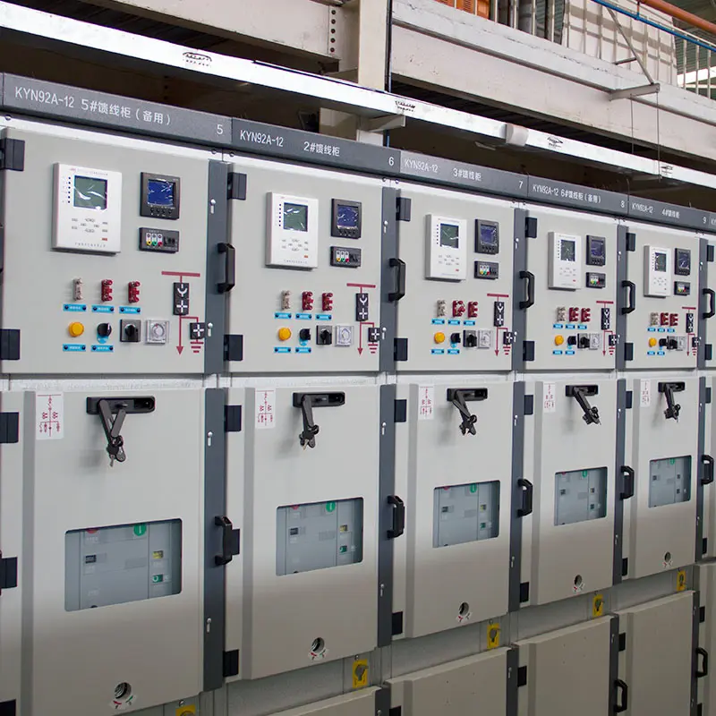
An electrical house that looks orderly on a single-line diagram can become a maintenance liability in physical space. Switchgear placement that ignores access clearance, thermal management, and future expansion creates conditions where routine breaker replacement requires shutting down adjacent feeders and cable congestion restricts airflow enough to derate equipment. Good layout is the difference between an electrical house operating predictably for 30 years and one requiring costly reconfiguration within five.
Access Clearance and Safety Compliance
NEC Article 110.26 requires minimum working clearance in front of switchgear based on voltage and opposite wall condition. For 480-volt switchgear with grounded opposite walls, the minimum depth is 3 feet. For 4,160-volt equipment, the requirement increases to 4 feet. These are minimums — actual maintenance often requires more. A technician removing a 200-pound breaker from a vertical cubicle needs at least 4.5 feet to maneuver onto a lifting cart.
Dedicated egress paths are equally critical. Switchgear in a U-shaped configuration with a single entrance traps personnel during an arc flash incident at the switchgear nearest the doorway. Two means of egress meeting NFPA 70E travel distance requirements should be a non-negotiable constraint.
Thermal Management in Confined Spaces
Switchgear generates heat proportional to the square of current flowing through bus bars and breakers. A 4,000-amp main bus at 80 percent load dissipates roughly 3,000 to 5,000 watts continuously. Without adequate ventilation, this raises interior temperature above the rated ambient — typically 40°C — causing accelerated insulation aging and trip unit drift.
Switchgear positioned perpendicular to airflow paths creates dead zones where heat accumulates. Layout should position sections parallel to the airflow from intake louvers to exhaust fans, with at least 24 inches of rear clearance. Electrical houses in hot climates should include forced-air ventilation sized for 10 air changes per hour at the switchgear heat load.
Functional Layout Principles
Feeder Grouping and Cable Management
Grouping switchgear by load location reduces cable length, voltage drop, and tray congestion. A chemical plant electrical house should position process-area feeders closer to the process-side cable exit and utility feeders closer to the utility exit. This grouping reduces average feeder cable length by 20 to 30 percent compared to sequential numbering ignoring physical location.
Cable entry and exit must be designed from the outset. Top-entry switchgear cannot accept bottom-fed cables without bus modifications. Bottom-entry switchgear on housekeeping pads above cable trenches requires precise coordination between manufacturer footprints and civil layout — a 100-millimeter mismatch forces field modifications compromising arc-resistant ratings.
Future Expansion Provisions
Layout should reserve space for at least 20 percent additional feeder breakers adjacent to the existing line-up. Bus duct connections to future sections should be specified at initial purchase — adding a bus extension without factory-prepared connection points is significantly more expensive.
A Practical Case: Food Processing Plant Electrical House Redesign
A food processing plant in the Netherlands operated switchgear from two manufacturers installed 12 years apart. The original layout placed newer switchgear against the rear wall with only 18 inches of clearance — code minimum but inadequate for maintenance. When a 1,600-amp main breaker required replacement, the entire section had to be de-energized for 14 hours because the lifting cart could not maneuver.
The plant redesigned the layout with full 48-inch front and 30-inch rear clearances. China Electrical supplied the new switchgear configuration, including dedicated bus duct connections for planned expansion. Cable tray routing was revised to separate power and control cables, eliminating signal interference that caused occasional nuisance trips. The reconfiguration extended major breaker replacement downtime from 14 hours to 4 hours per unit.
Layout Verification and Commissioning
Before pouring the foundation, physical mockup using floor marking tape confirms clearances are achievable. Every section should have front and rear access zones marked, and the path from doorway to every section should be walkable with a maintenance cart. After installation, infrared imaging at 25, 50, 75, and 100 percent of design load establishes baseline temperature rise. Hot spots exceeding 30°C above ambient indicate installation defects.
Frequently Asked Questions
What is the minimum clearance required in front of switchgear?
NEC 110.26 requires 3 feet for 480-volt equipment and 4 feet for 4,160-volt equipment. Maintenance access typically requires 4.5 to 5 feet for breaker removal in most configurations.
Why does switchgear layout affect cable costs?
Feeder grouping reduces average cable length by 20 to 30 percent compared to arbitrary arrangement. Cable cost savings from optimal layout typically exceed engineering study costs within the first 10 feeders.
How much expansion space should be reserved in a switchgear layout?
A minimum of 20 percent additional feeder positions adjacent to existing switchgear. Bus extension connection points should be specified at initial purchase to avoid expensive field modifications.
Does switchgear orientation affect cooling performance?
Switchgear parallel to airflow cools more effectively than perpendicular placement. Minimum 24-inch rear clearance with forced ventilation at 10 air changes per hour is recommended in hot climates.
What is the most common layout error in electrical houses?
Insufficient maintenance access despite meeting code minimums. Breakers requiring removal need significantly more space than code working clearances. China Electrical provides switchgear configuration guidance accounting for maintenance access beyond code minimums.
How do separate voltage levels affect switchgear layout?
Medium-voltage and low-voltage switchgear should be physically separated by at least 6 feet or a fire-rated barrier. Cable routing between voltage levels should avoid parallel runs that induce interference in control circuits.