EN
EN
 AR
AR
 BG
BG
 HR
HR
 CS
CS
 DA
DA
 FR
FR
 DE
DE
 EL
EL
 HI
HI
 PL
PL
 PT
PT
 RU
RU
 ES
ES
 CA
CA
 TL
TL
 ID
ID
 SR
SR
 SK
SK
 SL
SL
 UK
UK
 VI
VI
 ET
ET
 HU
HU
 TH
TH
 MS
MS
 SW
SW
 GA
GA
 CY
CY
 HY
HY
 AZ
AZ
 UR
UR
 BN
BN
 LO
LO
 MN
MN
 NE
NE
 MY
MY
 KK
KK
 UZ
UZ
 KY
KY
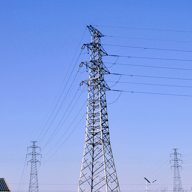
Core Structural Loads Acting on Power Towers
Gravitational loads: Conductor weight, hardware, and tower self-weight
The gravitational or dead loads on transmission towers include things like the weight of conductors, insulators, various hardware components, plus the tower itself. These constant downward forces usually make up around 60 to 70 percent of what engineers consider normal operating loads for these structures. Getting right the actual weights and material properties during initial design work matters a lot because mistakes here can lead to problems down the road such as gradual bending of materials, settling foundations, or components wearing out faster than expected. When designers underestimate these basic weights, it creates serious issues later on especially when weather related stresses come into play too.
Lateral loads: Wind pressure, dynamic gusts, and vortex shedding effects
Strong winds apply significant sideways pressure to towers and their supporting cables. Sudden gusts can create unexpected pressure spikes, and when wind flows around structural elements it creates something called vortex shedding. This oscillating pattern actually gets structures vibrating at their natural frequencies, which over time leads to cracks forming from repeated stress cycles. According to standards set by ASCE 7-22, any design built in areas prone to high winds needs to handle what's known as 50-year storm conditions. Cross bracing isn't just an extra feature added for good measure it's absolutely essential for proper load distribution. Without these cross supports in place, unchecked wind forces will wear down connections much faster and eventually undermine the whole structure's stability.
Environmental amplification: Ice accumulation and its nonlinear load magnification
When ice builds up on power lines, it turns regular gravitational forces and wind pressure into serious problems that aren't straightforward to calculate. Just 1 centimeter of ice around a conductor adds roughly 15 kilograms per meter to its weight while making the surface area hit by wind grow about 30 percent bigger. This combination can actually triple what the line has to handle mechanically during certain winter storm conditions. What makes things even worse is when ice forms unevenly across different parts of the line. This creates twisting forces and bending stresses that most standard designs simply weren't built to withstand. Looking ahead, NOAA's latest climate projections show we're likely facing a 30 percent increase in major ice storms and Category 4 hurricanes by 2040. Given these trends, engineers need to stop treating regional safety factors as optional extras and start incorporating them directly into their designs if we want our electrical grids to stay reliable through these increasingly extreme weather events.
Safety Margins and Regulatory Load-Bearing Standards for Power Towers
ASCE 7-22 and NESC 2023 requirements: 1.5× to 2.5× nominal load factors
The ASCE 7-22 standard along with the newer NESC 2023 regulations set out required safety margins that help account for uncertainties in modeling, variations in materials, and inevitable construction tolerances. According to these codes, engineers need to multiply load combinations by different factors depending on the situation. Routine dead plus live loads get multiplied by around 1.5 times, while those extreme scenarios involving wind and ice call for amplification up to 2.5 times. Some particularly important design situations involve calculating the maximum wind pressure against conductors, determining ice buildup according to NESC Table 250-1 for specific zones, and dealing with combined gravitational forces when multiple extreme conditions happen at once. Take lattice towers as an example. A tower built to handle 200 kN of normal conductor tension actually needs to withstand between 300 and 500 kN when all the safety factors are applied. This built-in redundancy helps ensure structural integrity while still keeping costs within reasonable limits for most projects.
Climate-resilience debate: Reassessing minimum safety margins amid intensifying wind/ice events
We're seeing more frequent and intense compound weather events lately, especially those involving wind and ice combinations. The old safety factors just aren't cutting it anymore. Those traditional 1.5 times multipliers completely miss how things get out of hand when even thin layers of ice meet strong winds. We've actually seen load measurements spike over three times what was expected in some cases. Groups like the Edison Electric Institute along with NIST's Grid Resilience folks are pushing for new multipliers that account for climate vulnerabilities. They want these changes implemented particularly in areas at higher risk, think places like the Midwest ice belt or the Gulf Coast where hurricanes hit regularly. There are plans to update ASCE 7 standards by incorporating local climate data so they can set minimum requirements above 2 times the current levels wherever history shows increasing dangers. This approach tries to find that sweet spot between spending money wisely and actually reducing risks we know exist.
Load-Bearing Capacity Under Extreme and Unbalanced Failure Scenarios
Conductor breakage: Sudden unloading and asymmetric tension redistribution
When conductors fail due to things like metal fatigue, galloping vibrations, or damage from severe storms, it leads to sudden tension losses in the system. These losses create imbalances that get passed along to neighboring spans and supporting towers. What happens next? The extra stress can cause structural problems like buckling in compressed parts or push anchor bolts past their breaking point. Engineers now build towers with special features that help them handle these unexpected forces better. They use advanced methods to analyze how loads move through structures and incorporate backup support systems so everything stays stable even if one conductor breaks. According to field tests, towers built according to the latest NESC Annex B standards for dynamic loading have cut down on chain reaction failures by around two thirds when compared with older static design approaches.
Unbalanced ice loading: Asymmetry-induced torsion, bending, and progressive collapse risk
When ice builds up unevenly on a tower or conductor set, it creates twisting forces and off-center bends that go way beyond what standard designs account for. This kind of imbalance actually causes most of the gradual collapses we see in older infrastructure systems, especially when metal parts have corroded over time or suffered previous damage that weakened critical connection points. To fix this problem, engineers need to focus not only on how strong materials are but also on their ability to bend without breaking and resist twisting forces. The real world tells us a lot too look at what happened during the big freeze in Texas back in 2021. Towers equipped with proper diagonal bracing across all sides and made with steel that can stretch rather than snap held up perfectly even though they had over 2 centimeters of ice forming on the windward side of their conductors.
Structural Reinforcement and Foundation Design for Optimal Tower Load-Bearing Performance
Bracing systems: Diagonal efficiency in resisting buckling, torsion, and sway
Diagonal bracing uses triangles to turn sideways forces and twisting motions into straight line forces, which makes materials work better while keeping things from bending too much. When dealing with compression members, good angle placement stops them from buckling under pressure simply by shortening their effective length. To fight against twisting caused by wind or uneven ice buildup, engineers often install cross bracing at right angles that create strong frame structures capable of resisting rotation. The actual angles where these supports are placed need careful calculation so they can hold buildings steady during movement but still allow for normal expansion when temperatures change. Studies published in professional journals indicate that quality bracing systems can boost load capacity by around 40 percent compared to buildings without such support. This kind of strengthening remains one of the best value options whether building something new or upgrading existing structures.
Foundation solutions: Drilled shafts vs. spread footings for overturning and soil-bearing demands
The kind of foundation used determines whether a tower can stand up against forces like overturning, lifting, and uneven settling. Drilled shafts, also known as caissons, go down around 15 to 30 meters into solid ground layers. These work really well in soils that stick together and areas with strong winds because they take advantage of both friction along their sides and support at the bottom. They provide better resistance against being lifted or flipped over while using less concrete overall compared to other options. Spread footings function differently. They need a broad base area usually four to eight times larger than the actual tower base itself. These tend to perform best when placed in compacted sandy or gravelly soils where the ground can handle significant weight without sinking. The downside? To match the same level of stability provided by drilled shafts during earthquakes or when soil gets wet, spread footings need about 60 percent more concrete. Before making any decisions though, getting detailed information about what's actually underground through proper geological testing is absolutely essential. Trying to pick foundations based on quick rules instead of real site conditions leads to most problems we see with towers failing in practice.
FAQ
What are gravitational loads on power towers?
Gravitational loads include the weight of conductors, insulators, hardware components, and the tower itself, making up about 60 to 70 percent of normal operational loads.
Why are lateral loads important to consider in tower design?
Lateral loads from wind can cause structures to vibrate and crack over time. Cross bracing helps distribute these forces to maintain stability.
How does ice accumulation affect power towers?
Ice accumulation increases weight and surface area, amplifying mechanical stress during storms and potentially leading to more severe twisting and bending.
What are the safety standards for power towers?
ASCE 7-22 and NESC 2023 outline load factors of 1.5 to 2.5 to account for uncertainties and extreme conditions like wind and ice.