EN
EN
 AR
AR
 BG
BG
 HR
HR
 CS
CS
 DA
DA
 FR
FR
 DE
DE
 EL
EL
 HI
HI
 PL
PL
 PT
PT
 RU
RU
 ES
ES
 CA
CA
 TL
TL
 ID
ID
 SR
SR
 SK
SK
 SL
SL
 UK
UK
 VI
VI
 ET
ET
 HU
HU
 TH
TH
 MS
MS
 SW
SW
 GA
GA
 CY
CY
 HY
HY
 AZ
AZ
 UR
UR
 BN
BN
 LO
LO
 MN
MN
 NE
NE
 MY
MY
 KK
KK
 UZ
UZ
 KY
KY
Voltage-Driven Design Constraints for Transmission Towers
Wind, ice, and electromagnetic loading at 230 kV and above
When dealing with voltages of 230 kV or higher, transmission towers encounter complex environmental stresses that don't just increase proportionally with voltage levels. During bad weather events, wind pressure can hit over 50 pounds per square foot, which means the side supports need serious reinforcement. This is particularly true for lattice style towers where the most stress builds up at the points where legs connect and where conductors are attached. Ice buildup presents another major challenge too. When ice accumulates to about two inches thick on conductors, it triples their weight, creating uneven tension across the system and causing twisting forces that engineers hate to see. At the same time, when fault currents pass through the lines at rates above 40 kA, they create powerful electromagnetic forces that cause conductors to whip around violently, sometimes setting off dangerous resonances in the tower itself. Because these different stress factors overlap so completely, engineers rely heavily on finite element analysis to understand how everything works together. For instance, at 400 kV systems, lattice towers generally need bracing that's somewhere between 20 and 30 percent stronger compared to monopole designs facing similar conditions.
Clearance and creepage distance compliance (IEC 61936 / IEEE 1243)
The need for electrical isolation gets much more demanding as voltages increase. According to standards like IEC 61936 and IEEE 1243, the required clearance between phases and ground grows significantly too. At 230 kV systems need at least 2.3 meters of space, but this jumps to 3.6 meters when operating at 345 kV levels. These numbers directly affect how tall transmission towers need to be built and how far apart their cross arms must sit. Insulator strings present another challenge since their creepage distances need scaling up as well. For polymer insulators specifically, we're looking at around 25 mm per kilovolt in areas with pollution problems to prevent those annoying surface tracking issues. When space becomes tight, engineers often turn to V-string configurations for insulators. But there's another persistent problem that keeps coming back: contamination. Salt fog or industrial residue buildup can cut flashover voltage down by nearly half in some cases. That's why regular cleaning schedules become absolutely necessary in regions where these contaminants tend to accumulate over time.
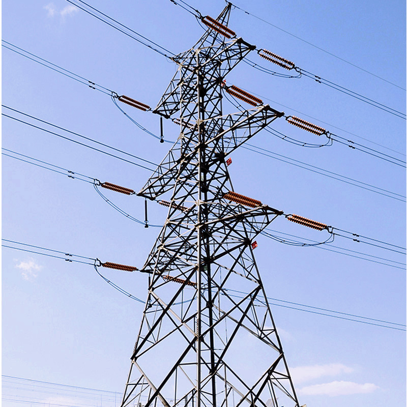
Tower Type Selection: Matching Structural Form to Function and Environment
Functional roles: suspension, tension, transposition, and crossing towers
The way power transmission towers work determines their physical shape and construction. Suspension towers hold up electrical wires straight up using those long strings of insulators we often see hanging from them, making them common sights along straight sections of power lines. When the path needs to change direction or cross over rivers, tension towers come into play. These are built specifically to handle the massive forces when one side of the line pulls harder than the other. There's also transposition towers which twist around the position of the three phases in the line so everything stays balanced across hundreds of miles. And then there are crossing towers that simply lift the wires high enough to clear roads, railways or mountains. Getting the wrong type of tower in the wrong spot can be dangerous business. Imagine putting a regular suspension tower at a sharp bend where it should be a tension tower instead. During storms or high winds, this mismatch could lead to failures spreading rapidly through the entire grid system.
Material and form trade-offs: lattice vs. tubular vs. monopole for 400 kV+ lines
Selection balances performance, logistics, and environment:
- Lattice towers, built from galvanized steel angles, deliver superior strength-to-weight ratios and modular scalability—making them the default for 400 kV+ projects requiring maximum load capacity and seismic resilience. Their triangulated geometry effectively dissipates dynamic energy, especially in earthquake-prone zones.
- Tubular steel poles offer reduced visual impact and smaller footprints, with sealed sections limiting corrosion exposure. However, transportation constraints cap practical heights for ultra-high-voltage applications.
- Monopoles, though faster to install and less land-intensive, incur steep material cost escalation beyond 230 kV. Their solid-wall construction provides excellent resistance to asymmetric ice loading—particularly advantageous in alpine terrain.
Core Structural Components and Load Path Integrity in Transmission Towers
From cross arm to foundation: ensuring continuous force transfer under fault conditions
The structural strength of these systems hinges on continuous load transfer starting at conductor attachments, moving through cross arms, along the tower body, and finally reaching the foundation. These cross arms take on various forces such as wind pressure, ice buildup, and electromagnetic effects before passing them along to the main structural frame. For lattice towers specifically, the load path happens through either bolted or welded joints that need built-in redundancy to stop buckling issues. Tubular and monopole designs work differently relying instead on strong flange connections between parts plus internal stiffeners for support. When it comes to foundations whether they're embedded directly into ground or constructed with grillage systems they must handle sudden load increases of around 2.5 times normal levels during incidents like when conductors snap unexpectedly according to industry standards set by IEC 61936:2020. Finite element analysis helps engineers see how stress spreads throughout all components, aiming to eliminate any possibility of failures at just one point in the system. Important factors to check during verification processes would typically involve...
| Verification Parameter | Normal Conditions | Fault Conditions |
|---|---|---|
| Joint Deflection | ≤ 0.2° | ≤ 1.5° |
| Base Plate Stress | ≤ 145 MPa | ≤ 240 MPa |
| Anchor Bolt Tolerance | ±5% | ±12% |
High-ductility steels (e.g., S460ML+) ensure plastic deformation rather than brittle fracture under overload. Corrosion-resistant coatings at connection points—validated for coastal or chemically aggressive sites—are maintained throughout service life to preserve load-path continuity.
Mechanical Strength Verification and Compliance for High-Voltage Tower Systems
When it comes to structural validation, engineers stick to well established international standards such as IEC 60652 for mechanical testing of overhead line components and ASCE 10-15 which deals specifically with steel transmission tower design. During full scale testing, prototypes get put through their paces with simulated conditions including wind speeds reaching 150 kilometers per hour, various vertical loads both dead weight and active loads, plus scenarios where wires break unexpectedly. These tests mimic the most extreme mechanical stresses that could ever occur in real life situations. To check how forces move through the structure, calibrated load cells measure pressure points while theodolites track any movement or displacement from cross arms all the way down to the foundation anchors. What we find after certification isn't just proof that everything meets regulations, but actually shows safety margins that go beyond what's required operationally by anywhere between 25% and 40%. This kind of thoroughness really matters because when something goes wrong in high voltage networks above 400 kilovolts, one failure at a critical point can cause problems stretching across several regions and jurisdictions.
FAQs
Why is finite element analysis important for high voltage transmission towers?
Finite element analysis is crucial as it helps engineers understand how different stress factors like wind, ice, and electromagnetic forces interact, allowing for optimal tower design and reinforcement.
What are the main differences between lattice towers and monopole designs?
Lattice towers offer superior strength-to-weight ratios ideal for high-capacity projects, while monopoles, easier to install and less land-intensive, incur higher costs beyond 230 kV, providing good resistance against ice loading.
How do compliance standards affect transmission tower design?
Compliance standards dictate the necessary clearance, creepage distances, and load capacities for safe operation, impacting material choice, tower dimensions, and overall design to handle environmental and operational stresses.