EN
EN
 AR
AR
 BG
BG
 HR
HR
 CS
CS
 DA
DA
 FR
FR
 DE
DE
 EL
EL
 HI
HI
 PL
PL
 PT
PT
 RU
RU
 ES
ES
 CA
CA
 TL
TL
 ID
ID
 SR
SR
 SK
SK
 SL
SL
 UK
UK
 VI
VI
 ET
ET
 HU
HU
 TH
TH
 MS
MS
 SW
SW
 GA
GA
 CY
CY
 HY
HY
 AZ
AZ
 UR
UR
 BN
BN
 LO
LO
 MN
MN
 NE
NE
 MY
MY
 KK
KK
 UZ
UZ
 KY
KY


The Engineering Foundation of Power Transmission
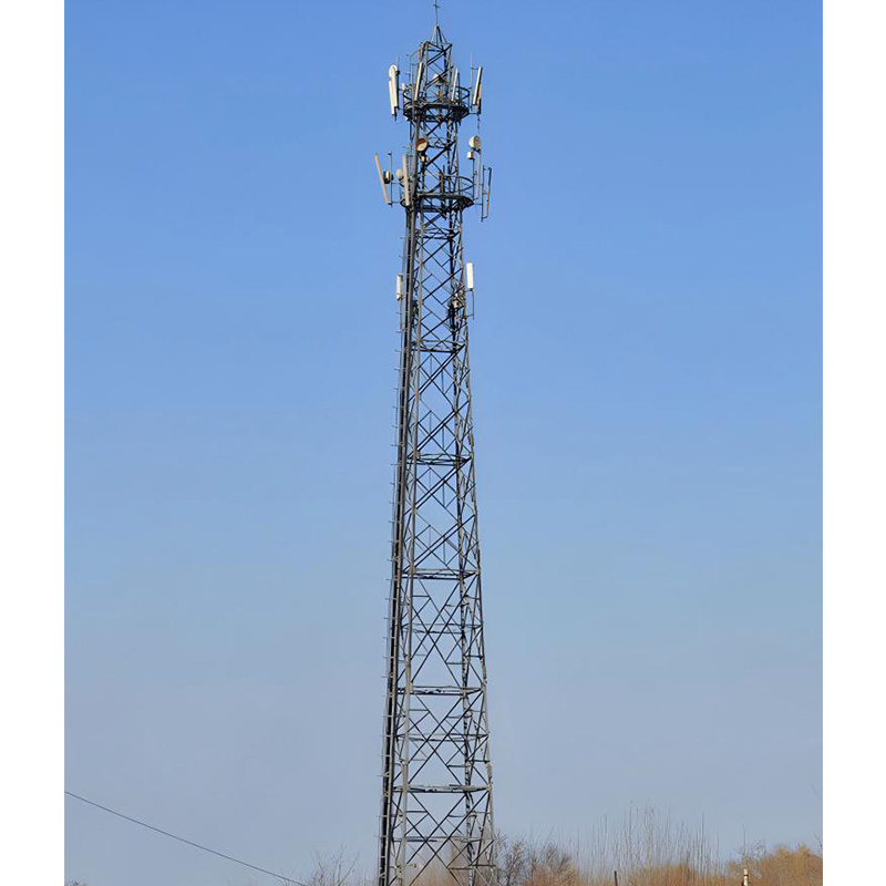
High-voltage transmission towers carry conductors across distances from hundreds of meters between substations to thousands of kilometers across national grids. Each tower must withstand static conductor weight, dynamic wind loads, ice accumulation, and electromagnetic forces during short-circuit events — all while maintaining clearances that prevent flashover.
Design begins with voltage level and conductor configuration, which determine height and cross-arm dimensions. A 132kV double-circuit tower rises 25–35 meters. A 400kV tower reaches 40–55 meters with wider cross-arms. Every additional meter adds steel weight, foundation concrete volume, and crane capacity requirements — multiplying costs across all project phases.
A transmission project crossing South American mountains replaced lattice towers with compact delta-configuration designs on slopes exceeding 15 degrees. The narrower footprint reduced foundation excavation by approximately 40% on steep terrain where concrete truck access was the project's largest logistics challenge.
Structural Design Specifications
Lattice Tower Geometry
Lattice tower structures use angle steel connected by bolted joints, creating truss systems that resolve loads through axial tension and compression rather than bending. This reduces steel weight by 30–50% compared to tubular poles of equivalent capacity.
The body follows a square or rectangular cross-section tapering from wide base to narrow top. Base width-to-height ratios of 1:6 to 1:8 for suspension towers and 1:4 to 1:5 for angle towers reflect the greater overturning moment at directional change points. Member sizing follows IEC 60826 loading criteria using 50-year return period wind data. Towers in hurricane-prone regions require ratings exceeding 200 km/h.
Foundation Design
Foundation type depends on geotechnical conditions. Spread footings suit competent soils above 200 kPa bearing capacity. Pile foundations transfer loads to deeper strata when surface soils consist of loose sand or soft clay. Rock-anchored foundations bolt tower stubs directly into bedrock — the most economical option when competent rock lies within 1–2 meters.
Uplift resistance often governs design over compressive bearing. Wind perpendicular to conductor spans creates uplift forces on the windward side exceeding structure dead weight. Foundations resist these cyclic forces for decades without gradual pullout that would tilt the tower and reduce phase-to-ground clearances below safe limits.
Material and Corrosion Protection
Structural steel conforms to ASTM A36 or S355JR grades, with higher-strength grades used selectively in heavily loaded members. Hot-dip galvanizing to ISO 1461 provides primary corrosion protection, with 85µm minimum coating for sections above 6mm thickness. Coastal installations within 5km of salt water require 100–140µm or supplemental paint systems.
Electrical Design Specifications
Insulation Coordination
Phase-to-ground clearance determines tower window dimensions. The switching surge factor — typically 2.0–2.5 per unit for systems above 245kV — multiplied by maximum system voltage defines the minimum air gap preventing flashover. IEC 60071 provides the insulation coordination framework.
Shield wire positioning creates a 30-degree or less protection angle from vertical in areas exceeding 10 lightning flashes per square kilometer annually, ensuring strikes attach to grounded shield wires rather than phase conductors.
Conductor Configuration and Bundling
Voltages above 220kV use bundled conductors — two, three, or four sub-conductors per phase separated by spacers at 30–60 meter intervals. Bundling reduces electric field gradient below the corona inception threshold that generates audible noise, radio interference, and ionization energy losses. Sub-conductor spacing of 400–500mm optimizes gradient reduction without creating sub-span oscillation risks.
Grounding System
Tower footing resistance below 10 ohms is the accepted target, though values up to 20–25 ohms are tolerated in high-resistivity soils. Counterpoise wires buried radially from each leg reduce resistance where vertical rods alone cannot achieve targets. The grounding system carries lightning stroke currents of 20–50kA peak without developing touch or step potentials exceeding IEC 60479 safety thresholds.
Frequently Asked Questions
What is the difference between suspension and angle transmission towers?
Suspension towers support conductors vertically along straight sections, bearing primarily vertical loads. Angle towers anchor conductors at directional changes, bearing full horizontal conductor tension. They use heavier members, wider bases, and larger foundations. Lines use suspension towers for 80–90% of length and angle towers at direction-change points.
How are transmission tower heights determined?
Conductor ground clearance at maximum operating temperature — when thermal expansion creates maximum sag — determines minimum height. Adding insulator string length, cross-arm depth, and shield wire peak height produces total height. Terrain requires taller structures at low span-profile points to maintain clearance above valleys and road crossings.
What wind speeds must transmission towers withstand?
Design wind speeds range from 120 km/h for sheltered inland locations to over 250 km/h for tropical cyclone regions. IEC 60826 categorizes terrain roughness and provides wind pressure calculations. Manufacturers like Liaoning Sinotech Group supply towers engineered for specific regional wind zone requirements.
Why are lattice towers preferred over tubular poles for high-voltage transmission?
Lattice towers use 30–50% less steel because truss configurations resolve loads into axial forces rather than bending moments. Lower weight reduces material and foundation costs. Bolted connections allow compact disassembled transport — 40 towers' worth of angle steel ships in containers holding only 8–10 equivalent tubular pole sections.
How do transmission towers handle ice loading?
Ice accumulation adds 2–10 kg per meter of conductor weight, multiplying total load by 3–8 times. Design accounts for simultaneous iced conductor weight and reduced wind loading — storms rarely coincide with maximum wind speeds. Asymmetric ice shedding creates longitudinal unbalanced loads that angle towers must resist.
What is the service life of a properly designed transmission tower?
Galvanized lattice steel towers achieve 50–70 year service life with periodic inspection. Corrosion at bolted joints where galvanizing wears thin is the limiting factor. Replacing individual angle members during scheduled maintenance extends life beyond 80 years, making lattice towers among the most durable grid infrastructure assets.