EN
EN
 AR
AR
 BG
BG
 HR
HR
 CS
CS
 DA
DA
 FR
FR
 DE
DE
 EL
EL
 HI
HI
 PL
PL
 PT
PT
 RU
RU
 ES
ES
 CA
CA
 TL
TL
 ID
ID
 SR
SR
 SK
SK
 SL
SL
 UK
UK
 VI
VI
 ET
ET
 HU
HU
 TH
TH
 MS
MS
 SW
SW
 GA
GA
 CY
CY
 HY
HY
 AZ
AZ
 UR
UR
 BN
BN
 LO
LO
 MN
MN
 NE
NE
 MY
MY
 KK
KK
 UZ
UZ
 KY
KY


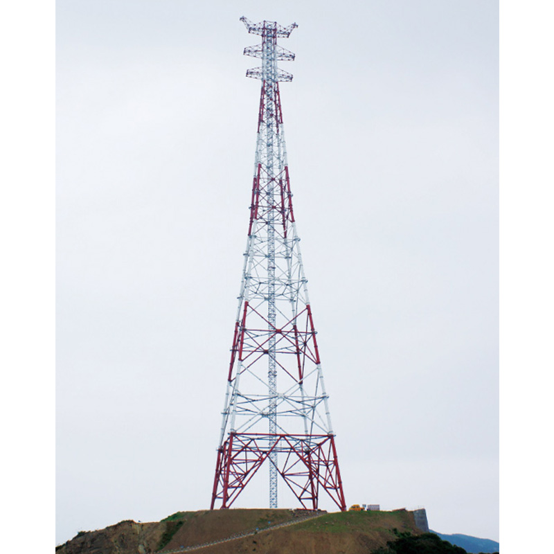
The Structural Backbone of Solar Farms
Photovoltaic support towers transfer solar panel weight, wind uplift, and snow loads into the ground while maintaining precise tilt angles for maximum energy yield. A utility-scale solar farm with 100,000 panels requires approximately 2,500–3,500 support tower structures depending on tracker or fixed-tilt configuration. Installation speed directly determines project economics — every delay postpones revenue from power purchase agreements typically valued at $30–80 per MWh.
A solar EPC contractor in the Middle East reduced per-megawatt installation time from 12 days to 7 days by switching from cast-in-place concrete foundations to driven steel piles with pre-assembled torque-tube sections. Eliminating concrete curing time — 72 hours per pour — accounted for most of the schedule improvement.
Foundation Installation
Geotechnical Survey and Selection
Geotechnical surveys sample soil conditions at 50–100 meter grid intervals, measuring bearing capacity, groundwater depth, and soil resistivity. These determine whether driven piles, helical screws, or concrete ballast provide the best foundation.
Driven steel piles — C-channel or H-beam sections — dominate installations on competent soils. A hydraulic pile driver installs 200–400 piles daily, embedding each 1.5–2.5 meters. Pull-out testing on 2–5% of piles verifies actual resistance matches assumptions, applying 1.5 times design uplift force.
Ground screw foundations suit sandy soils where driven piles lack lateral stability. Helical plates increase bearing area, and installation torque correlates directly with load capacity. If target torque cannot be achieved, the design switches to longer screws or larger helix diameters at that location.
Grading and Drainage
Solar arrays require slopes under 5% north-south. East-west slopes up to 10% work with adjustable mounting structures. Grading maintains drainage patterns preventing water ponding — saturated soil loses bearing capacity and accelerates corrosion at pile interfaces. Erosion control measures must be in place before grading begins.
Structure Assembly and Alignment
Torque Tube Installation
Single-axis tracker systems use torque tubes — continuous steel tubes running north-south — rotating panels to follow the sun. Sections arrive in 6–12 meter lengths with pre-welded bearing journals.
Alignment tolerances demand ±3mm over 80–100 meter rows. A misaligned bearing binds rotation, increasing drive motor force and potentially stalling during morning startup. Laser alignment tools verify bearing position before torque tube sections are bolted together.
Module Mounting
Aluminum rails bolted to support purlins provide the panel mounting surface, spaced to match module frame dimensions. Mid-clamps between adjacent modules and end-clamps at row ends secure panels with torque-limited bolts preventing glass cracking.
Teams of 3–4 workers place 200–300 modules daily. Quality control samples 5–10% of clamp torque and inspects for micro-cracks that propagate over thermal cycles into cell cracking within the first year.
Grounding Integration
Each tower row requires grounding conductors bonded to every metallic component. This prevents potential differences during ground faults and provides lightning current paths. Copper-clad steel conductors and below-grade connections reduce visible copper exposure that attracts theft at remote sites.
Commissioning and Verification
The tracker control system undergoes commissioning where each row's drive motor cycles through full rotation. SCADA verifies position matching within ±1 degree. Rows failing this test require mechanical troubleshooting — binding bearings, misaligned couplings, or installation debris.
Pull-out testing repeats on a sampling basis after all rows are installed, especially where soil conditions varied across the site. A foundation failing after module installation requires costly remediation, making pre-installation survey quality disproportionately important.
Frequently Asked Questions
How deep should photovoltaic support tower foundations be?
Driven piles embed 1.5–2.5 meters depending on soil type, frost depth, and wind loads. Frost heave requires pile tips below maximum frost penetration — 1.0–1.5 meters in temperate regions and 2.0+ meters in continental climates. Ground screws extend 1.2–2.0 meters with 150–300mm helix diameters.
What is the difference between fixed-tilt and tracker support towers?
Fixed-tilt structures hold panels at a constant angle optimized for annual yield. Tracker support towers rotate panels east-to-west, increasing energy capture by 15–25%. Trackers add 30–40% to support structure cost per watt through torque tubes, bearings, and drive systems.
How does soil type affect photovoltaic support tower installation?
Cohesive soils like clay provide good pile capacity through skin friction but may require pre-drilling at high density. Granular soils allow direct driving but need deeper embedment or ground screws for adequate pull-out resistance. Rocky soils may require concrete ballast foundations when neither piles nor screws can penetrate.
What corrosion protection do photovoltaic support towers require?
Hot-dip galvanizing to minimum 85µm per ISO 1461 protects for 25–30 years. Coastal installations within 5km of salt water require 100–140µm. Aluminum components naturally resist corrosion through passive oxide formation. Suppliers like Liaoning Sinotech Group provide support systems engineered for specific environmental conditions.
How long does complete photovoltaic support tower installation take?
A 100MW installation with driven piles requires 8–12 weeks for complete support structure work. Schedule varies with crew size, automation level, and terrain. Prefabricated components and rapid-deployment designs continuously reduce these timelines.
What quality checks are performed during installation?
Pull-out testing on 2–5% of foundations, torque verification on 5–10% of clamps, bearing alignment survey on every row, ground resistance measurement at 50–100 meter intervals, and tracker rotation testing on 100% of rows. Documentation supports warranty claims if structural issues develop during operation. The pre-installation geotechnical survey quality directly determines how many foundations require costly post-installation remediation.